RETURN HOME
Electric machine modeling
abc or phase-variable modeling:
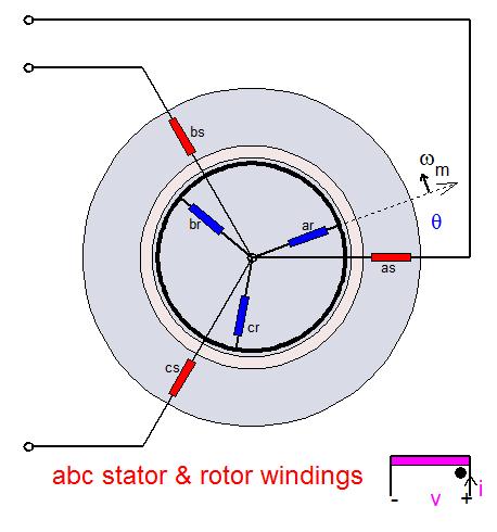
The first step in the mathematical modeling of an induction machine is by describing it as coupled stator and rotor three-phase circuits using phase variables, namely stator currents ias, ibs, ics and rotor currents iar, ibr, icr ; in addition to the rotor speed ωm and the angular displacement θ between stator and rotor windings. The machine electrical parameters are expressed in terms of a resistance matrix R [6x6] and an inductance matrix L [6x6] in which the magnetic mutual coupling elements are functions of position θ. The electrical variables V, I, λ appear as 6-element column vectors (in the matrix analysis connotation); so that, for instance, the current vector is I = [ias ibs ics iar ibr icr]t, representing stator and rotor currents expressed in their respective stator and rotor frames. While the matrix analysis of three-phase stator and rotor circuits in relative motion is easy to formulate mathematically (in particular using Matlab), it nevertheless obscures an understanding of the underlying physical interactions and does not directly lead to the introduction of control strategies.
dq transformations:
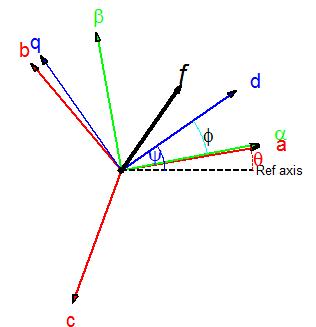
The next step is to transform the original stator and rotor abc frames of reference into a common ωk or dq frame in which the new variables for voltages, currents, and fluxes can be viewed as space vectors (in a 2-D geometric sense) so that currents are now defined as is = [ids iqs] and ir = [idr iqr].
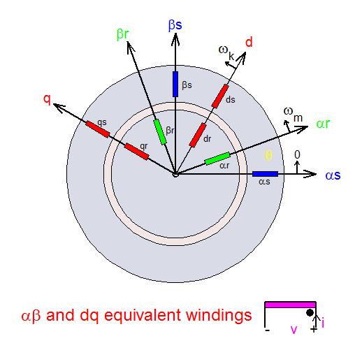
dq or space-vector modeling:
In the dq frame, the inductance parameters become constant, independent of position. Among possible choices of dq frames are the following: a) Stator frame where ωk = 0; b) Rotor frame where ωk = ωm; c) Synchronous frame associated with the frequency ωs (possibly time varying); d) Rotor flux frame in which the d-axis lines up with the direction of the rotor flux vector. Because it utilizes space vectors, the dq model of the machine provides a powerful physical interpretation of the interactions taking place in the production of voltages and torques, and, more importantly, it leads to the ready adaptation of positional- or speed-control strategies such as vector control and direct torque control.
Because of the asymmetry of the synchronous machine created by rotor saliency and field excitation, the corresponding dq model must use the rotor coordinates as reference frame.