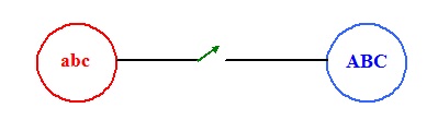
SYNCHRONIZATION
Two 3-phase power systems of differing frequencies are to be connected by
closing the breakers at the moment the voltages across them are minimum. The
phase voltages va, vb, vc of the
abc system
and the voltages vA, vB, vC of the
ABC system are represented in the left figure by
phasors of constant amplitude rotating at the speed associated with the
corresponding system frequencies. The voltages vaA, vbB, vcC
across the breakers are seen in the right figure as amplitude modulated phasors
rotating at the difference frequency (slip).